
Note
Go to the end to download the full example code.
Circuits#
Convert a Boolean circuit to an equivalent Boolean formula.
A Boolean circuit can be exponentially more expressive than an equivalent formula in the worst case, since the circuit can reuse subcircuits multiple times, whereas a formula cannot reuse subformulas more than once. Thus creating a Boolean formula from a Boolean circuit in this way may be infeasible if the circuit is large.
import matplotlib.pyplot as plt
import networkx as nx


def circuit_to_formula(circuit):
    # Convert the circuit to an equivalent formula.
    formula = nx.dag_to_branching(circuit)
    # Transfer the operator or variable labels for each node from the
    # circuit to the formula.
    for v in formula:
        source = formula.nodes[v]["source"]
        formula.nodes[v]["label"] = circuit.nodes[source]["label"]
    return formula


def formula_to_string(formula):
    def _to_string(formula, root):
        # If there are no children, this is a variable node.
        label = formula.nodes[root]["label"]
        if not formula[root]:
            return label
        # Otherwise, this is an operator.
        children = formula[root]
        # If one child, the label must be a NOT operator.
        if len(children) == 1:
            child = nx.utils.arbitrary_element(children)
            return f"{label}({_to_string(formula, child)})"
        # NB "left" and "right" here are a little misleading: there is
        # no order on the children of a node. That's okay because the
        # Boolean AND and OR operators are symmetric. It just means that
        # the order of the operands cannot be predicted and hence the
        # function does not necessarily behave the same way on every
        # invocation.
        left, right = formula[root]
        left_subformula = _to_string(formula, left)
        right_subformula = _to_string(formula, right)
        return f"({left_subformula} {label} {right_subformula})"

    root = next(v for v, d in formula.in_degree() if d == 0)
    return _to_string(formula, root)
Create an example Boolean circuit.#
This circuit has a ∧ at the output and two ∨s at the next layer. The third layer has a variable x that appears in the left ∨, a variable y that appears in both the left and right ∨s, and a negation for the variable z that appears as the sole node in the fourth layer.
circuit = nx.DiGraph()
# Layer 0
circuit.add_node(0, label="∧", layer=0)
# Layer 1
circuit.add_node(1, label="∨", layer=1)
circuit.add_node(2, label="∨", layer=1)
circuit.add_edge(0, 1)
circuit.add_edge(0, 2)
# Layer 2
circuit.add_node(3, label="x", layer=2)
circuit.add_node(4, label="y", layer=2)
circuit.add_node(5, label="¬", layer=2)
circuit.add_edge(1, 3)
circuit.add_edge(1, 4)
circuit.add_edge(2, 4)
circuit.add_edge(2, 5)
# Layer 3
circuit.add_node(6, label="z", layer=3)
circuit.add_edge(5, 6)
# Convert the circuit to an equivalent formula.
formula = circuit_to_formula(circuit)
print(formula_to_string(formula))


labels = nx.get_node_attributes(circuit, "label")
options = {
    "node_size": 600,
    "alpha": 0.5,
    "node_color": "blue",
    "labels": labels,
    "font_size": 22,
}
plt.figure(figsize=(8, 8))
pos = nx.multipartite_layout(circuit, subset_key="layer")
nx.draw_networkx(circuit, pos, **options)
plt.title(formula_to_string(formula))
plt.axis("equal")
plt.show()
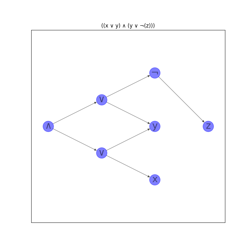
((x ∨ y) ∧ (y ∨ ¬(z)))
Total running time of the script: (0 minutes 0.089 seconds)